Revit to Reality:
The 1:1 Precision Alignment Workflow
True spatially registered BIM AR for active jobsites. The OnsiteBIM Alignment Target is the physical bridge locking your 3D BIM model directly over physical columns, shear walls, and floor slabs with sub-centimeter mathematical accuracy and zero drift.
The 4-Step Revit to Field Workflow
How BIM managers, VDC coordinators, and field superintendents lock 3D building models onto active jobsites in minutes.
Drop Target in Revit
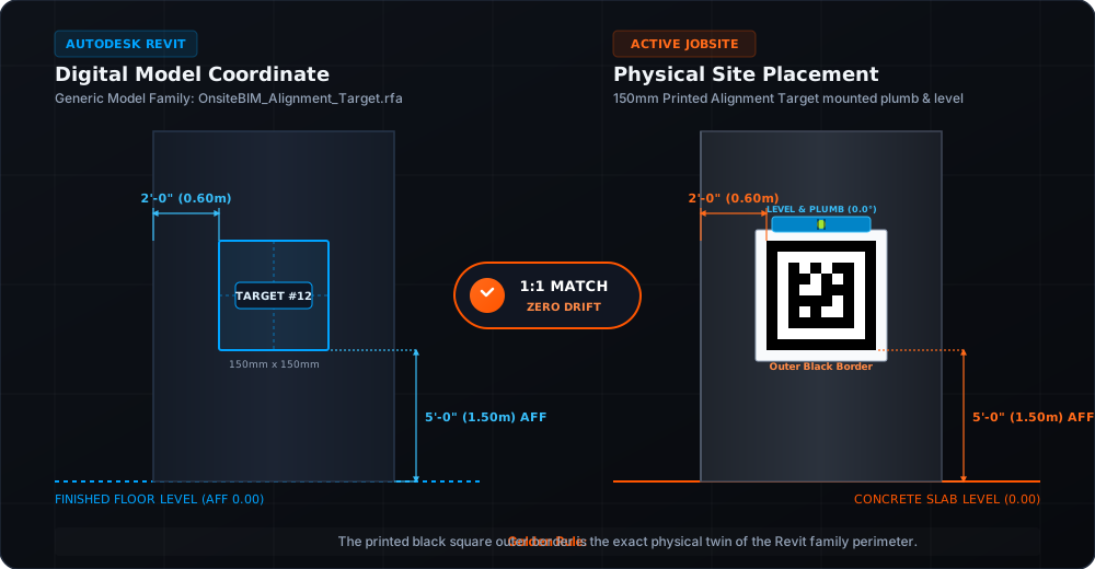
Drag OnsiteBIM_Alignment_Target.rfa into your Revit model. Snap it directly to a column face, wall surface, or floor benchmark that physically exists on site (e.g. Column Grid A-1, 1.50m / 5'-0" above finished slab).
1-Click IFC Export
In Revit, go to File → Export → IFC → Modify Setup → Import, select IFC Configuration - OnsiteBIM.json, and click Export.
Print & Mount on Site
Print the matching 150mm Alignment Target at 100% actual size from our free generator. Using a tape measure and torpedo level, tape the target to that exact column face on site at the identical offset.
Point Camera & Inspect
Open OnsiteBIM on your iOS or Android device, load your .ifc model from device storage or company cloud, and point the camera at the target. Your 3D building model instantly locks into place at true 1:1 life-size scale.
Open Slab vs. Room-Locked AR: Why Target Anchoring Wins
Traditional mobile AR tools require enclosed walls and finished room perimeters to calculate alignment. OnsiteBIM anchors directly to structural grid datums — inspecting pre-pour decks weeks before interior walls or rooms exist.
Room-Locked Positioning
- Requires Enclosed Walls: Needs finished drywall, ceilings, or room perimeters to register spatial geometry.
- Fails on Pre-Pour Decks: Cannot track on open concrete slabs, metal decking, or structural steel framing.
- Mandatory Cloud Uploads: Forces proprietary cloud hosting, slow processing queues, and vendor lock-in.
Open Slab Datum Anchoring
- Direct Structural Anchoring: Mounts to raw column faces, perimeter footings, or floor benchmarks using printed Alignment Targets.
- Pre-Pour Clash Verification: Verify plumbing sleeves, electrical penetrations, rebar clearance, and anchor bolts before concrete placement.
- 100% On-Device Processing: Zero cloud accounts, zero file conversions — models load instantly from local device storage or company cloud.
The 3 Golden Rules of Precision Placement
Follow these three rules to achieve sub-centimeter alignment between your Revit model and the physical jobsite.
Measure to the Black Square Border
The perimeter outline of the Revit family represents the exact outer edge of the black square on the printed target — not the edge of the paper margin. When measuring elevation (AFF) or corner distance, always measure from your site datum to the edge of the printed black square.
Level on Site = Level in AR
Mount the paper target strictly plumb and level using a standard torpedo level. Because the optical camera calculates orientation with high precision, a 2-degree physical tilt of the paper target on the column causes the virtual 3D building model to tilt by 2 degrees in AR.
Verify 100% Print Scale
Printers often default to "Fit to Printable Area", which shrinks targets by 3–5%. Always print at 100% / Actual Size, and verify the printed sheet with a tape measure against the built-in 50mm metric or 2.0-inch imperial calibration bars printed directly on every sheet.
Understanding Accuracy & Real-World Field Tolerances
Transparent engineering standards: distinguishing computer vision mathematical precision from physical field installation and long-distance tracking.
Optical Computer Vision Precision
At close standoff distances (1–3 meters), the device camera calculates exact 3D spatial position and orientation from the 150mm Tag36h11 code matrix with 1 to 3 mm mathematical precision. Tag36h11 features a 36-bit payload with a minimum Hamming distance of 11, making false-positive target identification mathematically impossible.
Field Installation Alignment
On-screen AR precision directly reflects your physical mounting accuracy. If a printed target is taped 2 degrees out of plumb on a column face, the virtual building model will tilt by 2 degrees in 3D space. Adhering to the 3 Golden Rules (torpedo level, black border measurement, and 100% print scale) ensures datum parity with your Revit model.
Motion Tracking Drift Management
As you walk through large floorplates, mobile motion tracking sensors naturally accumulate slight drift (typically 0.5% to 1% of distance walked over 20+ meters). Placing secondary Alignment Targets across building bays allows field inspectors to instantly reset motion tracking coordinates to zero drift simply by glancing at the nearest target.
The Role of OnsiteBIM: As-Built Verification & Visual QA/QC Field Instrument
OnsiteBIM is engineered as a rapid, high-precision visual QA/QC and as-built comparison instrument. By snapping your 1:1 scale model directly to known site benchmarks, field engineers and inspectors can use the live 3D clearance tape measure to verify construction tolerances (Δx, Δy, Δz) across all major trades—including pre-pour concrete sleeves, rebar clearances, structural steel framing, HVAC ductwork, hydronic piping, and drywall partitions. It is designed to work alongside, not replace, optical total stations or robotic laser scanners used for legal boundary layout and structural anchor bolt setting.
Get the Free OnsiteBIM Revit Toolkit
Everything your BIM & VDC team needs to connect Autodesk Revit 2024+ to the physical jobsite.
Complete Revit Toolkit (.ZIP)
Includes OnsiteBIM_Alignment_Target.rfa (face-based Revit 2024+ family), IFC Configuration - OnsiteBIM.json (1-click export profile), 2-page Field SOP Guide, and README.
2-Page Field Guide (PDF)
A handy printable 2-page Standard Operating Procedure (SOP) for site superintendents, surveyors, and field inspectors covering target mounting and scale verification.
Alignment Target Generator
Generate calibrated single sheets or batch ranges (IDs 0–586) at 15cm, 10cm, or 5cm with dual metric/imperial calibration rulers and vector PDF export.
Open Target Generator →Frequently Asked Field Questions
Detailed answers on coordinate systems, file export setups, and jobsite tolerances.
In Revit or your BIM coordination model, place the OnsiteBIM Alignment Target at a known grid intersection or benchmark on the floor slab and export via the 1-click IFC profile. On the jobsite deck, tape the matching printed target to that physical coordinate. Point your iPhone or iPad at the target to superimpose 3D sleeve and pipe penetrations directly onto the rebar and formwork at 1:1 scale before concrete placement.
Yes, 100%. OnsiteBIM is engineered to be local-first. 3D geometry parsing, optical target tracking, and rendering execute entirely on-device without cloud server handshakes. Simply copy your .IFC or 3D models to your device storage or Apple Files app before heading into subgrade levels.
Yes. You can assign different Target IDs (from 0 to 586) across different building wings or levels in Revit (e.g. Target #12 on Level 1 Column A-1, Target #14 on Level 2 Column C-4). Walking up to any target and aiming your camera re-anchors your model coordinates instantly.
Traditional room-boundary tools rely primarily on enclosed room perimeters, finished walls, or ceiling boundaries to calculate visual AR alignment. This approach cannot function on raw, pre-pour concrete slabs or open steel structural decks where walls do not yet exist. In contrast, OnsiteBIM anchors directly to structural column faces and grid datums using printed Alignment Targets. This gives field superintendents and MEP trades the unique ability to inspect sleeves, underground pipe rough-ins, and rebar clearances on open slabs weeks before interior partitions are framed. Additionally, OnsiteBIM requires zero proprietary cloud accounts, operating 100% locally on-device with your existing company cloud storage.

Ready to See Your 3D Models on Site?
Download OnsiteBIM for iOS or Android today. Test immediately with preloaded MEP duct models or load your own OpenBIM IFC files.